
|
|
|
The acronym ‘PERT’ stands for Program Evaluation and Review Technique. The purpose of a PERT Diagram is to schedule events and activities so time and timing are optimised. There are three components of a PERT Diagram:
1. Activities represented by arrows. These are things that must be done and take a specified time – often labelled by letters. 2. Events represented by circles. These are points in time, usually the end of one activity and the start of the next – labelled by numbers. 3. Non-activities (or dummy activities). These are shown as a dotted arrow between two events and indicating a dependency between the events. 
PERT Diagrams are most useful if they show the time scheduled for the completion of an activity on the activity line. The horizontal projection of the connecting arrows being drawn so as to represent the amount of time required for their activity. Time is recorded in a unit appropriate to the project (days, hours, weeks, or months). Some diagrams show two numbers for time estimates – a high estimate and a low estimate. Calculations may also be made as to the cost of reducing the time for an activity. In the process of diagramming to scale, some connecting arrows will be longer than the completion of that task requires. This is because of the slack time in the project and the latter is depicted by a heavy dot at the end of the appropriate time period, followed by a dashed-line arrow connecting to the following event. In diagrams not drawn to scale, the latest finishing time of an activity and the earliest starting time of the following activity are noted near or in the event circle along with the difference in the figures which is the slack. Steps for drawing a PERT diagram1. Develop a Focus for the project or process.
2. List the activities (steps) to achieve the outputs and outcomes and give them an identifying letter. 3. Make an estimate of the time to complete each step. 4. Determine which activities or steps precede or follow each other. 5. Draw up the network of relationships keeping in mind the sequencing. 6. Number the events (nodes or circles) for convenience. 7. The time taken for each activity is shown on the arrow. Steps that can be under way at the same time are shown on different paths. If you have a step that does not have a specific time it is not included in the PERT Diagram even though it has to be done. Be sure that all the relevant elements in your project have been included. A PERT Diagram not only shows the relationship along the various steps of the project, but also serves as an easy way to calculate the critical path. The critical path is the longest path through the network and as such identifies the essential steps that must be completed on time to avoid delay in completing the project. The critical path is usually shown as a heavy or coloured line. The usefulness of the PERT Diagram can be increased by colouring each step as it is completed. Actual time can be written over estimated time to maintain a running tally of actual versus planned time along the critical path. An example PERT Diagram is shown below: 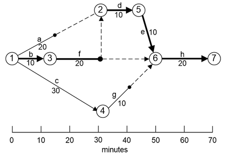
|
|